Difference between revisions of "Symbolic/Examples/Circuits"
| Line 41: | Line 41: | ||
Note that all elements except for <math>i_a</math> are labeled passively. | Note that all elements except for <math>i_a</math> are labeled passively. | ||
=== Code === | === Code === | ||
| − | The code for this example is available for download: | + | The code for this example is available for download: <html><a href='http://dukeegr93.com/Files/Circuit1Demo.mw' target="_blank">Circuit1Demo.mw</a></html>. You can also look at a [[:File:Circuit1Demo.pdf|PDF]] of the code. |
Revision as of 21:54, 12 September 2014
Contents
Brute Force 1
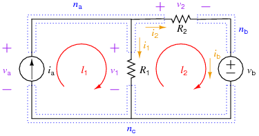
The following example shows the "brute force" method of setting up and solving for all the element currents and voltages for a simple resistive circuit and then using those solutions to solve for auxiliary information (in this case, some powers). The circuit involved is:
Equations
Element Equations
Mainly, these are Ohm's Law equations for the resistors, so:
KCL Equations
The number of independent KCL equations s one less than the number of nodes, so in this case, 2. Note: all three nodal KCL equations are written below, but node \(n_c\)'s is not used in the Maple worksheet.
KVL Equations
The number of independent KVL equations is equal to the number of meshes for a 2-D circuit, or to the number of elements, minus the number of nodes, plus one for circuits in general. In this case, that is 2 independent KVL (two meshes, or 3 elements - 3 nodes + 1 = 2). For the brute force method, just use the mesh equations:
Auxiliary Equations
For this example, the auxiliary equations will be used to determine the power delivered by each source and the power absorbed by each resistor:
Note that all elements except for \(i_a\) are labeled passively.
Code
The code for this example is available for download: Circuit1Demo.mw. You can also look at a PDF of the code.
